Concepts

  • The term magnetic effect of electric current means that an electric current flowing in a wire produces a magnetic field around it.
  • Hans Christian Oersted (1777-1851): Oersted showed that electricity and magnetism are related to each other. His research later used in radio, television etc. The unit of magnetic field strength is named Oersted in his honour.
  • Electromagnetism: In 1820, Oersted performed an experiment to show that a current flowing through a wire produces a magnetic field around it.
    • In this experiment, he found that when a magnetic needle was placed under a wire having no current flowing through it, the needle remained parallel to the wire as shown in the figure.
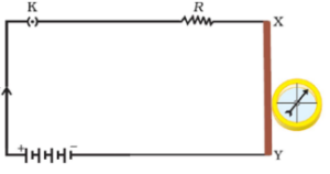
    • But when electric current was allowed to flow through it by connecting it with a battery, a deflection was observed in the magnetic needle showing that a current carrying wire produces a magnetic field around it, which lasts as long as the current is flowing through the wire.
    • This phenomenon is referred to as electromagnetism.
  • Magnet: A magnet is an object, which attracts pieces of iron, steel, nickel and cobalt. It has two poles at ends – South and North Pole.
    ➢ Like magnetic poles repel each other.
    ➢ Unlike magnetic poles attract each other.
  • Magnetic Field : The space surrounding a magnet in which the force of attraction and repulsion is exerted is called a magnetic field.
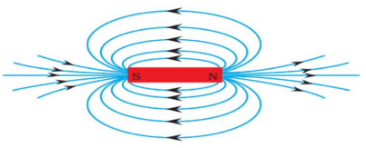
  • Magnetic Field Lines: A field line is the path along which a hypothetical free north pole would tend to move. The direction of the magnetic field at a point is given by the direction that a north pole placed at that point would take.
Properties of Magnetic Field Lines

  • A magnetic field lines originate from north pole and end at its south pole.
  • A magnetic field line is a closed and continuous curve.
  • The magnetic field lines are closer near the poles of a magnet where the magnetic field is strong and farther apart where the magnetic field is weak.
  • The magnetic field lines never intersect each other.
  • A uniform magnetic field is represented by parallel and equidistant field lines.
  • Field lines are shown closer together where the magnetic field is greater.
  • Magnetic field is a vector quantity.

Magnetic Field Due To a Current through A Straight Conductor

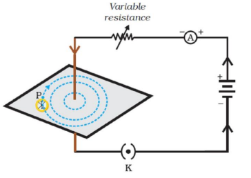
The magnetic field lines around a straight conductor carrying current are concentric circles whose centres lies on the wire.
The magnitude of magnetic field produced by a straight current carrying wire at a point-

  • directly proportional to current passing in the wire.
  • inversely proportional to the distance of that point from the wire.
Right-Hand Thumb Rule

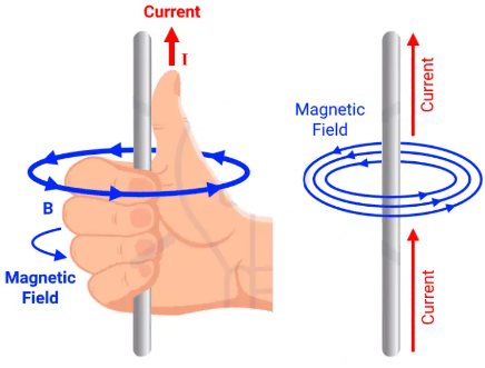
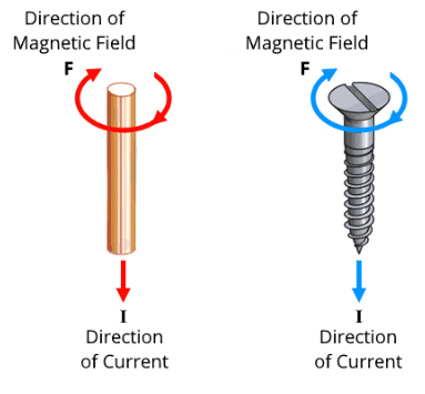
When a current-carrying straight conductor is holding in right hand such that the thumb points towards the direction of current. Then fingers will wrap around the conductor in the direction of the field lines of the magnetic field, as shown in below figure. This is known as the right-hand thumb rule. Also known as Maxwell’s Right Hand Thumb Rule.
Magnetic Field Due To a Current through a Circular Loop
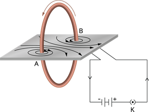
  • The magnetic field lines are circular near the current carrying loop. As we move away, the concentric circles becomes bigger and bigger.
  • At the centre, the lines are straight.
  • At the centre, all the magnetic field lines are in the same direction due to which the strength of magnetic field increase.
  • The strength of the magnetic field can be increased by taking a circular coil consisting of a number of turns of insulated copper wire closely wound together.
  • If a circular coil has 'n' turns, the magnetic field produced by this current-carrying circular coil will be 'n' times as large as that produced by a circular loop of a single turn of wire
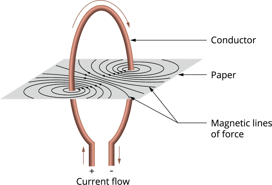
The magnetic of magnetic field produced by a current carrying circular loop at its centre is

  • directly proportional to the current passing.
    • B ∝ I
    • Where , B−Magnitude of the magnetic field , I−Current
  • inversely proportional to the radius of the circular loop.
    • B ∝ 1/r
    • Where , B−Magnitude of the magnetic field r−Radius of the circular wire

Magnetic field due to a current in a solenoid

  • A coil with number of circular turns of insulated copper wire covered closely in the shape of a cylinder is called a Solenoid.
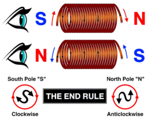
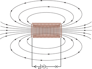
                             

  • The solenoid is from greek word for channel.
  • The solenoid is a long coil containing a large number of close turns of insulated copper wire.
  • The magnetic field produced by a current carrying solenoid is similar to the magnetic field produced by a bar magnet.
  • The current in each turn of a current carrying solenoid flows in the same direction due to which the magnetic field produced by each turn of the solenoid ads up, giving a strong magnetic field inside the solenoid.

Applications:

  • The strong magnetic field produced inside a current-carrying solenoid can be used to magnetise a piece of magnetic material like soft iron, when placed inside the solenoid.
  • The magnet thus formed is called an electromagnet.

The strength of magnetic field produced by a carrying current solenoid depends on

  • number of turns(n)
  • strength of current(I)
  • nature of core material used in solenoid – use of soft iron as core in a solenoid produces the strongest magnetism.

Electromagnets and Permanent Magnets

  • An electromagnet is a temporary strong magnet and is just a solenoid with its winding on soft iron core.
  • A permanent magnet is made from steel. As steel has more retentivity than iron, it does not lose its magnetism easily.
Increase magnetic field strength in a solenoid by,
  • Increasing the current flowing through it,
  • Increasing the number of turns on the coil per unit length,
  • Inserting a soft iron core into the solenoid.

Why soft iron is used for making the core of an electromagnet?

  • Soft iron is used for making the core of an electromagnet because soft iron loses all of its magnetism when current in the coil is switched off.

 Why steel is not used for making the core of an electromagnet?

  • Steel is not used for making the core of an electromagnet because steel does not loses all of its magnetism when current in the coil is switched off.

Force On a Current-Carrying Conductor in a Magnetic Field

An electromagnet is a temporary strong magnet and is just a solenoid with its winding on soft iron core. A permanent magnet is made from steel. As steel has more retentivity than iron, it does not lose its magnetism easily.

When a current carrying conductor is placed in a magnetic field it experiences a force, except when it is placed parallel to the magnetic field.
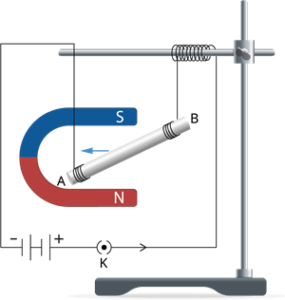
The force acting on a current carrying conductor in a magnetic field is due to interaction between:
1. Magnetic force due to current-carrying conductor and
2. External magnetic field in which the conductor is placed.

Fleming’s left-hand rule
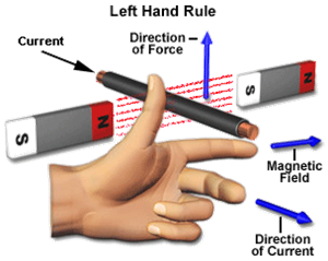
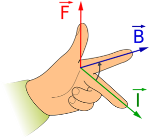
According to Fleming's left-hand rule, stretch the thumb, forefinger and middle finger of your left hand such that they are mutually perpendicular (as shown in the figure). If the first finger points in the magnetic field direction and the second finger in the current direction, then the thumb will point in the direction of motion or the force acting on the conductor.
Devices that use current-carrying conductors and magnetic fields include,
  • Electric motors
  • Electric generators
  • Loudspeakers
  • Microphones, and
  • Measuring instruments
Electric motor:
An electric motor is a type of rotating device. It converts electrical energy to mechanical energy. The electric motor is used as an essential component in electric fans, refrigerators, mixers, washing machines, computers, MP3 players, etc.,
Principle: When a coil carrying current is placed in a magnetic field, it experiences a torque. As a result of this torque, the coil begins to rotate.
Construction:
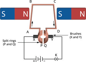
  • Armature :- the armature ABCD consists of a large number of turns of insulated copper wire wound over a soft iron core.
  • Field magnet :- the magnetic field (B) is supplied by a permanent magnet NS.
  • Split-ring or commutator :- These are two halves of the same metallic ring(P and Q). The ends of the armature coil are connected to these halves which also rotate with the armature. The inner sides of these halves are insulated and attached to an axle.
  • Brushes or sliding contacts :- these are two flexible metal plates or carbon rods X and Y which are so fixed that they constantly touch the revolving rings.
How does an electric motor works?
Current in the coil, ABCD starts to flow from the source battery through conducting brush X and return to the battery through brush Y. Notice that the current in arm AB of the coil flows from A to B. In arm CD, the current flows from C to D. The current flows through the arm CD opposite to the current direction through the arm AB.
Fleming’s left-hand rule is applied here to find the direction of the force on a current-carrying conductor in a magnetic field (see the below figure).
We can observe that the force acting on arm AB drives it downwards while the force acting on arm CD drives it upwards. Thus, the coil and the axle O are positioned free to turn about an axis, rotate anti-clockwise. At half rotation, Q is in contact with the brush X and P with brush Y. Hence, the current in the coil gets reversed and flows along the path DCBA.
The commutator is a device that reverses the direction of the flow of current through a circuit. In electric motors, the split ring works as a commutator. The reversal of current in a circuit also reverses the direction of force acting on the arms AB and CD. Therefore, the arm AB of the coil that was previously pushed down is now pushed up, and the arm CD earlier pushed up is now pushed down. So the coil and the axle rotate half a turn more in the same direction. The reversing of the current is done at each half rotation, providing rise to a continuous rotation of the coil and the axle.
The commercial motors use:
  • An electromagnet replaces the permanent magnet.
  • A conducting wire with a large number of turns in the current-carrying coil.
  • A soft iron core on which the coil is wound.
The soft iron core, on which the coil is wound, plus the coils, is called an armature. This improves the power of the motor.
Electromagnetic Induction : The process in which a changing magnetic field in a conductor induces a current in another conductor is called Electromagnetic induction.
The induced current is observed to be the highest when the direction of motion of the coil is at right angles to the magnetic field.
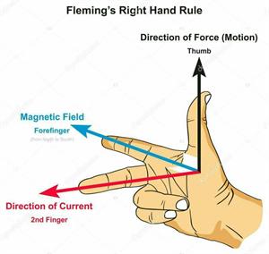
Stretch the right hand's thumb, forefinger, and middle finger perpendicular to each other, as shown in the below figure. Suppose the forefinger indicates the direction of the magnetic field, and the thumb shows the direction of motion of the conductor. In that case, the middle finger will show the direction of the induced current. This simple rule is called Fleming's right-hand rule.
Moving magnet in a fixed conductor

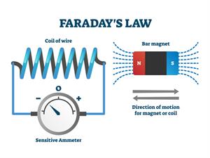
In 1831, English physicist Michael Faraday first studied this; Faraday made a significant breakthrough by discovering how a moving magnet can be used to generate electric currents.

To observe this effect, let us perform the following activity.

  • Consider a coil of wire AB having a large number of turns.
  • Connect the ends of the coil (AB) to a galvanometer, as shown in the below figure.
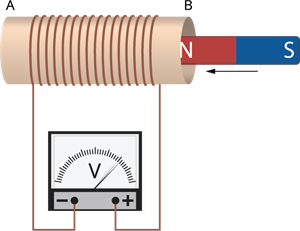
  • Take a strong bar magnet and move its north pole towards the end B of the coil.
  • Do you find any change in the galvanometer needle?
There is a transient deflection in the needle of the galvanometer, say to the right. This deflection shows the presence of a current in the coil AB. The deflection becomes zero the moment the motion of the magnet stops.
  • Now withdraw the north pole of the magnet away from the coil.
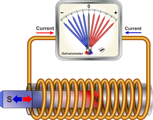
The galvanometer is deflected toward the left, showing that the current is set up opposite to the earlier deflection.
Moving a magnet towards a coil sets up a current in the coil circuit, as indicated by deflection in the galvanometer needle
  • Locate the magnet stationary at a point near the coil, maintaining its north pole towards the end B of the coil.
We can observe that the galvanometer needle deflects toward the right when the coil is moved towards the magnet's north pole. Similarly, the needle moves toward the left when the coil is moved away.
  • When the coil is kept stationary with respect to the magnet, the deflection of the galvanometer drops to zero.
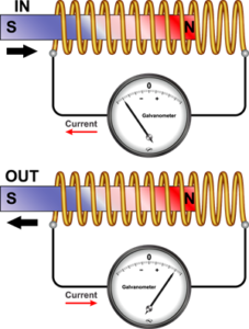
What do you conclude from this activity?
You can also check that if you had moved the magnet's south pole towards the end B of the coil, the deflections in the galvanometer would just be opposite to the previous case. When the coil and the magnet are both stationary, there is no deflection in the galvanometer.
It is, thus, clear from this activity that the motion of a magnet with respect to the coil produces an induced potential difference, which sets up an induced electric current in the circuit.
Summary:
The below table shows the relationship between the position of a magnet and the deflection in the galvanometer.
Position of a magnet
Deflection in galvanometer
Rest
No deflection
Moves towards the coil
Deflection in galvanometer in one direction
Kept stationary at the same position (near the coil)
No deflection in the galvanometer
Moves away from the coil
Deflection in galvanometer but in the opposite direction
Kept stationary at the same position (away from the coil)
No deflection in the galvanometer
Activity on electromagnetic induction
Let us now perform a variation of previous activity in which a current-carrying coil replaces the moving magnet, and the current in the coil can be varied.
Steps:
  • Take two different coils of copper wire with a large number of turns (say 50 and 100 turns, respectively) and insert them over a non-conducting cylindrical roll, as shown in the below figure (You may use a thick paper roll)
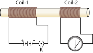
Current is induced in coil-2 when current in coil-1 is changed.
  • Connect the coil-1, which has a larger number of turns, in series with a battery and a plug key. Also, connect the other coil-2 with a galvanometer, as shown in the figure.
  • Plug in the key. Notice the galvanometer.
  • Is there a deflection in the galvanometer's needle?
You will see that the needle of the galvanometer immediately jumps to one side and just as quickly returns to zero, indicating a momentary current in coil-2.
  • Disconnect coil-1 from the battery.
You will see that the needle momentarily moves but to the opposite side. It indicates that now the current flows in the opposite direction in coil-2.
Observations:
In this activity, we see that as soon as the current in coil-1 reaches either a steady value or zero, the galvanometer in coil-2 shows no deflection.
This activity shows that whenever the electric current through coil–1 changes (starting or stopping), the potential difference is induced in coil-2. Coil-1 and coil-2 are known as the primary and secondary coils, respectively. As the current in the first coil varies, then the corresponding magnetic field also changes. Thus, the magnetic field lines around the secondary coil (coil -2) also change.
Hence the change in magnetic field lines associated with the secondary coil is the cause of induced electric current in it. This is called Electromagnetic induction.

Faraday's law electromagnetic induction

From that activity, we found that the motion of a magnet with respect to the coil produces an induced potential difference, which sets up an induced electric current in the circuit.

This process is called Electromagnetic induction.

Electromagnetic induction:

Electromagnetic or magnetic induction is the process of creating an Electromotive Force (EMF) or potential difference or voltage across an electrical conductor in a changing magnetic field. It is also produced when an electrical conductor is constantly moving in a stationary magnetic field.

Faraday discovered that certain factors affect this production of voltage or potential difference.
They are:
  • Number of Coils: The induced voltage or potential is directly proportional to the number of turns/coils of the wire. The greater the number of turns, the greater is the voltage or potential difference produced.
  • Changing Magnetic fieldInduced voltage or potential difference is affected by changing the magnetic field. This can be done by either moving the magnetic field around the fixed conductor or moving the conductor in the stationary magnetic field.
Faraday's law of Electromagnetic induction:

First law:

Whenever a coil in the magnetic field causes an Electromotive Force (EMFto be induced in the coil, this emf induced is called Induced emf. The current will also flow through the circuit if the conductor circuit is closed, called induced current.

Faraday's Second law:
Faraday's second law states that the magnitude of emf induced in the conductor is equal to the rate of change of flux that linkages with the coil. The flux linkage of the coil is the product of the number of turns in the coil and flux associated with the coil.
Applications of Electromagnetic induction:
  • Electromagnetic induction in AC generator
  • Electrical transformers
  • Magnetic flow meter
  • Electric guitars and Electric violins

Galvanometer:

galvanometer is an instrument used to detect and measure the current in an electric circuit.
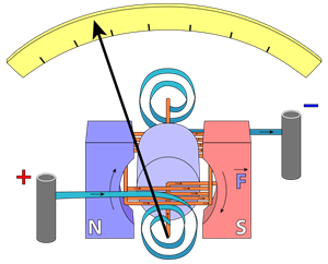
A galvanometer has a needle attached to a coil mounted to rotate freely within a magnetic field created by the poles of one or more permanent magnets. When the current is allowed to pass through the coil, the magnetic field generated by the current-carrying wire interacts with the field of the permanent magnets (travelling from north to south poles), generating a twisting force known as torque that rotates the coil, a response explained by the left-hand ruleThe deflection of the galvanometer’s needle is proportional to the current flowing through the coil.
The pointer stays at zero (the midpoint of the scale) for zero current flowing through it. Based on the current direction, the pointer can deflect either to the left or to the right of the zero mark.

Electric generators

In an electric generatormechanical energy is used to rotate a conductor in a magnetic field to generate electricity. It works on the principle of electromagnetic induction.
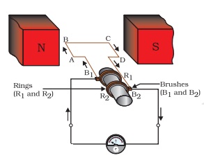
As shown in the figure, an electric generator contains a rotating rectangular coil ABCD located between the two poles of a permanent magnet. The two ends of this coil are attached to the two rings R1 and R2. The inner side of these rings is insulated. The two conducting brushes B1 and B2, are kept stationary and pressed separately on the rings R1 and R2, respectively. The two rings, R1 and R2, are internally connected to an axle.
The axle may be mechanically rotated from outside to rotate the coil inside the magnetic field. The outer ends of the two brushes are attached to the galvanometer to record the current flow in the given external circuit. When the axle connected to the two rings is rotated, the arm AB moves up (and the arm CD moves down) in the magnetic field created by the permanent magnet, let us say the coil ABCD is rotated clockwise in the arrangement as shown in the below figure.
By applying Fleming's right-hand rule, the induced currents start to flow in these arms along with AB and CD's directions. Thus, an induced current in the circuit flows in the direction of ABCD. If there are more numbers of turns in the coil, the current created in each turn adds up to provide a large current through the coil. This suggests that the current in the external circuit flows from B2 to B1.
After half rotation, arm CD begins to move up, and AB moves down. Due to this, the directions of the induced currents in both the arms (AB and CD) change, providing rise to the net induced current in the direction DCBA. The current in the external circuit starts to flow from B1 to B2. Thus, after every half rotation, the polarity of the current in the respective arms changes. Such a current, which changes direction after equal intervals of time, is called an Alternating Current (abbreviated as AC). This device is called an AC generator.
A split-ring type commutator must be used to get a direct current (DC, which does not change its direction with time). With this arrangement, one brush is at all times in contact with the arm moving up in the field, while the other is in contact with the arm moving down. We have seen a split ring commutator working in the case of an electric motor. Thus, a unidirectional current is produced. The generator is thus called the DC generator.
The difference between the Direct and Alternating Currents (DC and AC) is that the direct current always flows in one direction, whereas the alternating current reverses its direction periodically. Most power stations constructed these days produce AC.
In India, the AC changes direction after every 1/100 second; that is, the frequency of AC is 50Hz. An important advantage of AC over DC is that electric power can be transmitted over long distances without much energy loss.
Domestic electric circuits
In our homes, we receive a supply of electric power through the main supply (also called mains), either supported through overhead electric poles or underground cables. One of the wires in this supply, generally with red insulation cover, is called live wire (or positive). Another wire with black insulation is known as neutral wire (or negative). In India, the potential difference between the two is 220V.
At the metre-board in the house, these wires pass into an electricity meter through the main fuse. Through the main switch, they are attached to the line wires in the house. These wires provide electricity to separate circuits within the house. Usually, two separate circuits are used, one of 15A current ratings for appliances with higher power ratings such as electric heaters, geysers, air coolers, microwaves, etc., the other circuit is of 5A current rating for bulbs, fans, televisions, radios, etc.,
  • The current rating is the maximum current that a fuse will carry for an indefinite period without the fuse element's deterioration.

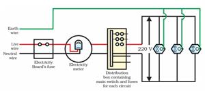
The earth wire, which has green colour insulation, is generally attached to a metal plate deep in the earth near the house. This is used as a safety measure, particularly for appliances with a metallic bodyfor example, electric press, microwave, toaster, table fan, refrigerator, etc. The metallic body is attached to the earth wire, which provides a low-resistance conducting path for the current. Thus, it assures that any leakage of current to the metallic body of the appliance keeps its potential to that of the earth, and the user may not get a severe electric shock.
The above diagram shows a schematic diagram of one of the standard domestic circuits. Separate appliances can be attached across the live (positive) and neutral (negative) wires in each separate circuit. The flow of current through each appliance is controlled (ON/OFF) by separate switches. Each appliance has an equal potential difference, and they are connected parallel to each other.
An electric fuse is a crucial component of all domestic circuits. In the previous chapter, we have already studied the principle and working of a fuse. A fuse in a circuit prevents damage to the electrical appliances and the circuit because of overloading.
Overloading can happen when the live wire and the neutral wire come into direct contact. (This happens when the insulation of wires is damaged or there is a defect in the appliance.) In these situations, the current in the circuit suddenly increases. This is called short-circuiting.
The electric fuse prevents the electric circuit and the appliance from possible damage by preventing excessively high electric current flow. The Joule heating that takes place in the fuse melts it to break the electric circuit. Overloading can also happen due to an accidental hike in the supply voltage. Sometimes overloading is caused by connecting too many appliances to a single socket.
The precautions that should be taken to prevent the overloading of domestic circuits:
  • Two different circuits should be used, one of 5 A current and the other 15 A current.
  • For both 5 A and 15 A circuits, we should install the fuse.
  • Parallel circuits should be used.
  • Never connect too many electrical appliances at the same point.
  • Never use too many electrical appliances at the same time.
  • We should not connect damaged appliances in the circuit.